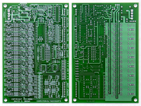
Dave sent me a schematic earlier this week that is 98% complete.  I'm
converting that to my own CAD system and am almost done.  I started a rough
PC board placement just to see how things fit.  It is clear that I won't be
able to support all the power connectors out there.  The board is only 85 mm
x 30 mm, or 3.346 inches x 1.181 inches.  Blacet/MOTM, Modcan,
Synthesizers.com and Doepfer style power connectors would take up almost
half the board.

As most kit builders use Blacet or MOTM formats, I'll place the 4/6 pin
Blacet/MOTM footprint.  All other builders will have to solder their power
cable directly to the board, or use a power cable that adapts their format
to Blacet or MOTM 4 or 6 pin power connectors.

I'm assuming that this won't be powered from the CVS PCB, especially
considering the recent discussions expanding the analog inputs and outputs
which puts more power consumption on the CVS PCB.

The following signals are connected between CVS and LCD Support PCBs, using
a 0.100 inch header:
1.  MIDI RX (TX from CVS)
2.  Reset
3.  Ground

It appears there is not much interest in Dave's idea looping the MIDI
through this PCB, which would add a TX back to the CVS.  This allows him to
filter out the "educational" coded MIDI signals, making the CVS MIDI spec
compliant in the real world.

If Grant and Harry can confirm the above CVS to LCD Support PCB connector
pinout, I should have everything I need to layout the LCD Support PCB.

John Loffink
The Microtonal Synthesis Web Site
http://www.microtonal-synthesis.com
The Wavemakers Synthesizer Web Site
http://www.wavemakers-synth.com


[Non-text portions of this message have been removed]
Message
LCD Support PCB update
2006-03-19 by John Loffink
Attachments
- No local attachments were found for this message.