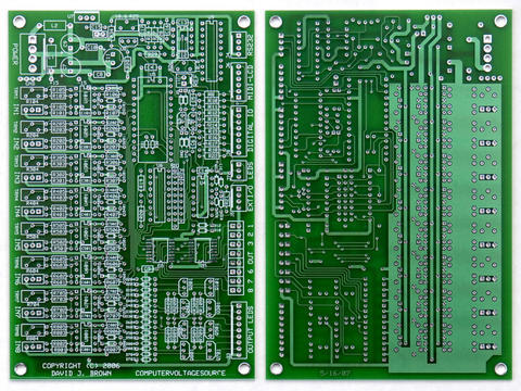
Looks like a nice layout. I would be a little careful about the row of 8 LEDs on the
very right side of the panel. They seem to be a little close to the edge. This may
be a problem depending on how one plans to mount the LEDs (say, on a little PCB
or some such thing. If one glues them directly on the panel then there would be
no problem.


--- In ComputerVoltageSources@yahoogroups.com, "Norman Fay" <vietgrove@...> wrote:
>
> I uploaded my frac-format front panel as it's progressing so far to
> the files section.  It needs:
>
> midi sockets w/screw holes
> screw holes for the lcd screen (I'll make up a macro for this)
> screw holes for PCB mounting to panel
> some labelling
> probably loads of other stuff as well.
>
> As it is, the left 2/3 of the panel is (top down)
>
> the 8 attenuator pots
> the 8 offset pots
> the 8 general-purpose VC in jacks
> the 8 calibrated 1v/oct CV in jacks
>
> These need to be labelled, and the order they're in can of course be
> altered.  My little pot tick macro is based on a bunch of knobs I have
> left over from an abortive diy modular I attempted to make years ago.
> They're the same shape as MOTM knobs, but 2cm across,  I think they're
> the same size as those used on the black-panel Wiard 1200 modules.
> The pot ticks stick out 1mm/1.5mm around the edges of the pots.
> They're rather close together - there's a 2mm gap between the edges of
> the knobs, if there are used, though obviously Blacet-style knobs, or
> Wiard 300/Serge style knobs could be used instead.  I just chose those
> ones b/c I have a box full spare, and they look nice.  The tick marks
> can be easily deleted, or shortened for smaller knobs of course.
>
> The next section is the LCD window - I got the viewing area dimensions
> from the .pdf file in the files section, below that are some holes for
> controls - run and stop both have a larger hole for an LED holder at
> the top - I measured some LED holders I have - probably smaller ones
> are available that would look neater, then next down a hold for a
> push-switch, again I measured a small switch I have, then a jack hole
> at the bottom.
>
> To the left of that, a hole for the reset pushbutton, a hole for the
> aux i/o jack, then the RS232 connector.   If I rotate the RS323 hole
> by 90 degrees and move the i/o socket up, there'll be a little bit
> more room for a pair of MIDI sockets below the run/stop section.
>
> To the left of this are the 8 output sockets holes, each with a hole for an LED.
>
> I'm quite pleased w/it so far, but of course it might be crap.  Let me
> know what you think please people!
>
> Thanks.
>
Message
Re: frac format front panel so far
2006-04-01 by Michael A. Firman
Attachments
- No local attachments were found for this message.