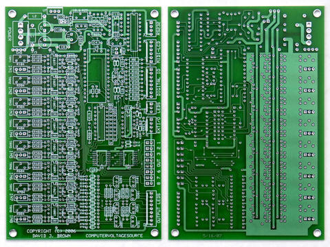
This was what I was thinking:

DIN Sync (24ppq) clock goes into the PSIM

PSIM software reads the output of one of the sequencer's pot rows and
uses this to determine the step length (1/32, 1/16, 1/8, etc) in terms
of those incoming clock ticks.  After playing with a Roland System 700
sequencer, this is a must-have feature.  I've done this with my PSIM &
CGS Sequential Switch and it is a blast!

The PSIM also determines the "mode" from a CV input.  Forward, Reverse,
Pendulum Odd, Pendulum Even, Random, Binary Walk, etc.  This is why the
multiplexing is needed; you have to be able to assign *any* step as the
active one via the software to do some of these modes.

Then the PSIM feeds the multiplexing bits to the 4067 chip which then
feeds 10v to the appropriate step (column) of the sequencer, which is
really just a bunch of 16 channel mixers.  The PSIM also provides the
Gate, but that has nothing to do with the sequencer at this point, it
just goes out to the synth's EGs.

Here's what I need HELP to know how to do:

Since it's multiplexed, having SKIP available on each step is easy in
the software, but how do you have 16 hardware on/off switches so that
the PSIM can easily tell which are On and which are Off?

Can you feed voltage thru these 16 switches, and then to another 4067
chip as 16 inputs, then feed the 4 bits to the PSIM?

Ideally I'd want to have *two* rows of on/off switches that could be
constantly "sniffed" by the PSIM for various functions.

Along the same lines, is there a way to for one voltage to be converted
into bits (0000~1111) so that just *one* PSIM output can give the
multiplexer the "which step to be active" information?


Andrew,  small brain/big ideas  :)

>>> "djbrow54" <davebr@...> 12/16/06 11:50 AM >>>
It's been designed so the 8 analog inputs can be multiplexed (with no
external inputs) to read 16 potentiometers.  My intentions are to
write a sequencer for it, somewhat emulating the ARP sequencer.  You
should be able to do 16x1, 8x2, sequential or random.  The exact
features are left to be designed but with the display I can do a
pretty decent interface.  There really aren't enough inputs / controls
to do a decent internal clock so I am thinking of using the edge-
detect interrupts on the Aux input for a clock.  That will give really
low latency.  The Start and Stop switches can be used to go into a
setup mode and select various parameters such as mode, skip, etc.
Specific outputs would be trigger and gate.

Another interesting possibility is to use the CVS for the sequencer
and use a PSIM for the clock generation. The PSIM could generate the
clock with a CV and FM input. I can write a serial (e.g. MIDI)
protocol
to sync the two if necessary.  However, if I can't think of any extra
features to put in it, one might as well just use an LFO as the clock.

Dave

--- In ComputerVoltageSources@yahoogroups.com, "Andrew Scheidler"
<xpandrew@...> wrote:
>
> I am hoping to build the step sequencer of my dreams, using the "CVS
> thing" as the brain.
>
> I've done this in a limited way with a Metalbox/CGS Sequential
Switch
> and a PSIM-1.  For example, the DIN SYNC clock goes into the PSIM,
which
> then uses the voltage at IN4 to determine the gate time (in 24ppq
ticks)
> to feed the sequencer via OUT4.
>
> But to really do what I want, I need to address the individual
steps.
> This would allow the Atom24 to point at specific steps instead of
always
> going sequentially.  So things like "random" sequence and "skip"
would
> be possible.  (right?)
>
> (this is multiplexing, correct?  any good resources on this on the
web?)
>
> I'd be interested in hearing anyone else's thoughts...
>
> Andrew
>
> ps - Happy Birthday Grant !
>
Message
Re: [ComputerVoltageSources] Re: Sequencers
2006-12-18 by Andrew Scheidler
Attachments
- No local attachments were found for this message.