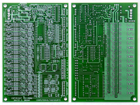
Brice designed the PSIM board with a 40 pin socket for the AtomPro.
If you remove the AtomPro24 and replace it with an AtomPro28, you get
four additional pins.  There is an on-board reset circuit on the
AtomPro28 that doesn't like it's output grounded (the guys at
BasicMicro disagree with me on this) but shorting reset to ground with
a switch will blow the part.  You just need to put a resistor in
series with the switch.  I think I used 47R (I wrote it down
somewhere).  The four additional pins are then connected to square
pins on the PSIM board.  Fly some wires off to an auxiliary board and
you can buffer them for whatever.  You can use them as four additional
analog inputs, digital inputs, or outputs.  There is one constraint
that one of the 8 inputs must be analog (so you can't set all to
digital - who would?)

For additional digital inputs or outputs, you can expand the PSIM with
I2C.  There is a two pin jack for P6 and P7 which can be used to
expand the I/O.  I have an I2C to RS-232 and an I2C to MIDI that I
use.  I have also tested the PSIM with an MCP23008 I2C to 8 bit port
expander.  This will give you any combination of digital inputs and
outputs.  This is what I plan on using to control the second DAC and
programmable reference voltages on the CVS.  I used 5 of the 8 pins
with 3 spare.  All you need is two pullup resistors and there is even
room on the PSIM board to add these.  You can see my schematic for an
I2C to RS-232 to drive the TTS-256/SpeakJet at
http://modularsynthesis.com/modules/synthmodules/PSIM-SpeakJet/PSIM-
speakjet.htm  (sorry - long link)

I have an AtomPro FAQ on my
http://modularsynthesis.com/modules/synthmodules/synthmodules.htm
page.  The link is just above the programs.  Some of this is
documented in there along with some timing information.  Reading
digital inputs via I2C isn't that fast as you have a number of bytes
for the transfer.  Outputs are pretty quick.

Lots of opportunities.  This is basically what the CVS design is with
a second DAC for 8 analog outputs, MIDI, and programmable references
so you can read 16 potentiometers.

However, we're stalled at the PCB layout.  I'm ready to give up and
just hand wire my board.

Dave

--- In ComputerVoltageSources@yahoogroups.com, "Andrew Scheidler"
<xpandrew@...> wrote:
>
> Moe -
>
> The AUX can be the Gate Out of course, but I must have one input &
> output for note quantization  :)
>
> There must be some way to take *one* PSIM output and turn that into
> addresses 0~15.
>
> On the MiniWave, the Wave Selection input voltage is somehow
converted
> into binary, which then lights up the 4 leds;  that's what I'm
thinking
> about.   So 0~0.5v = 0000, 0.6~1.0v=0001, 1.1v~1.5v=0010, etc.   The
> PSIM program could specify the sequencer step 1~16 by outputting   =
> 0.25v*requiredstepnumber.
>
> I don't yet understand how 16 skip switches can all communicate with
the
> PSIM.  If there is a way to do that using just one PSIM input?  With
> another multiplexer you could scan across all the switches between
> steps, but I don't think the DAC could be scanned 16 times and still
be
> fast enough at even moderate tempos.  (?)
>
> I guess you could (assuming the switches were multiplexed)
>    #1) choose which step to go to next
>    #2) look at the status of that switch's SKIP switch
>    #3) if SKIP=on then go back to step #1
>    #4) go ahead and fire up that step
> But this could result in noticable delays if several SKIPs were ON.
>
> If you dedicated two PSIM inputs to 16 on/off switches, you'd have
20
> bits to work with, yes?  Would that make it possible?
>
> I feel like the greatest hardware step sequencer is just a couple
minor
> problems away...
>
> Andrew
>
>
> >>> "Dave Bradley" <mate.stubb@...> 12/18/06 12:22 PM >>>
> Andrew,
>
> If the 4 psim outputs were set up to be a binary address, you could
have
> complete specification of any arbitrary number between 0 and 15.
>
> Then set up two inputs as you described, one for control of clock
pulse
> advancement for rhythm, and one for control of direction/next stage
> select
> mode.
>
> Set up a third input as a skip input.
>
> Aux would be an output that fires a pulse every time the state
changes
> for
> envelopes. The width could be controlled up to 100% by the 4th
input.
>
> Now you need a pot matrix with binary inputs, kind of like what I
was
> trying
> to do with SuperMoe:
>
> http://www.hotrodmotm.com/images/CV_Generator_8x4new.jpg
>
> This module can do 8x4 steps, 16x2 steps, or 32x1 steps. Since you
only
> have
> 4 psim outputs for address, you could do 2 rows of 16 steps worth of
> control, randomly accessible from the psim.
>
> Moe
>
> On 12/18/06, Andrew Scheidler <xpandrew@...> wrote:
> >
> > Dave -
> >
> > Can the existing PSIM-1 have four more inputs added?  Outputs too?
> >
> > Are there schematics or instructions for this somewhere?  I have a
> > soldering station and I'm not afraid to use it  :)
> >
> > Andrew
> >
> > >>> "djbrow54" <davebr@...> 12/16/06 11:50 AM >>>
> > It's been designed so the 8 analog inputs can be multiplexed (with
no
> >
> >
> >
> >
> >
> > Yahoo! Groups Links
> >
> >
> >
> >
>
>
> --
> Dave Bradley
>
>
> [Non-text portions of this message have been removed]
>
Message
Re: Sequencers
2006-12-19 by djbrow54
Attachments
- No local attachments were found for this message.