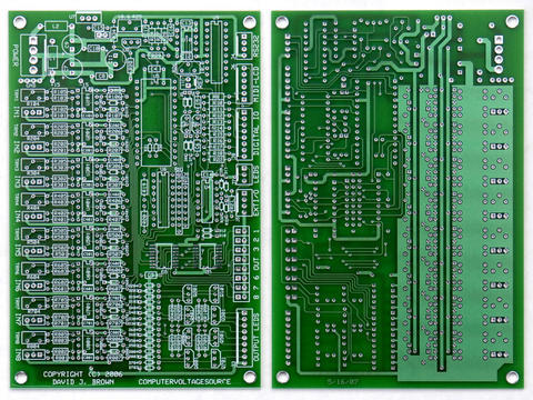
My $0.02 on the subject ...

I just picked a feature set that appealed to me and designed it using
a lot of work that others had done. I don't have professional layout
tools and so I just did a prototype using ExpressPCB.  The issue is
that quicks are not very affordable. I paid $120 for two boards
without solder mask. 10 mil runs and spacing without solder mask is
not fun to build. The setup fee for solder mask is ~$220. That's
why I haven't posted the PCB files. I did post the schematics and I
have continued to post modifications.

I've been soldering for over 40 years (boy I'm getting old!). I ended
up using head magnifiers along with a hand loupe looking for shorts. I
had three on my board that took me a while to find (and took out
several parts). There are over 50 wires connecting to the board so you
don't just turn it over and look on the back side. In addition, my
board format is too small; I used a 4" x 6" board size. I couldn't get
the MIDI components on (although John put the MIDI circuitry on the
LCD support PCB - thanks!) and my recent modifications do not fit. I
had to go to 1/8W resistors to get the I2C protection to fit and the
input filter capacitors have to be piggybacked on the feedback
resistors. I was hoping that someone with PCB skills and tools would
volunteer to layout a larger PCB with gerber output so the boards
could be more affordable.

In retrospect, I would change my design. The 0 to 10 and +/- 5 volt
input selection is great. I might eliminate the extra 8
potentiometers and just have done this selection with switches. I
wanted the extra potentiometers for a sequencer which I would do now
using I2C.

The 8 output leds are either on or off - there isn't much dynamic
range. I probably should have used a 2x40 or 4x16 display instead of
a 2x16 and just reserved 8 character positions for output indicators.
I have written code to display vertical bars on the LCD that work fine
(although I am not volunteering to do so now!). It would have taken a
larger AVR for the LCD Support design, though. Even with 32 characters
I had to abbreviate a lot of the MIDI patch names to get them to fit
for my sequencer.

Someone suggested a more modular design. I think this is a good idea.
My input filters to reduce noise limit the imput frequency of the
analog inputs. While not a problem due to the limited processing
speed of the AtomPro, I have to wait 7 mS when reading each bank of 8
potentiomenters to let the filters settle. It would have been cheaper
to eliminate the switching reference supplies and just use them to
normalize the inputs. The I2C expansion is a less expensive way to
add 8 additional potentiometers (and faster since I don't have to wait
for the input filters!).

I could see a design using 4 modular boards:
1. Processor with 8 input / output and voltage references
2. Connector / potentiometer interconnect to minimize panel wiring
3. LCD Support for display and MIDI
4. I2C expansion for additional analog and digital inputs

All this group needs is to arrive at a consensus of features and
someone to do the PCB layout. I personally don't feel like there is
enough interest to arrive at a common feature set so whoever does the
layout would get to choose the features.

I have always been open to sharing the PCB design files for those that
are up to the challenge. So far very few have asked. It's also a very
expensive module. Price out 16 potentiometers ($3-$8 ea), knobs ($1-
$2 ea), PCB ($60-$120 for quicks), LCD ($18), processor ($60) and
front panel ($100) and you are already over $300 without any of the
remaining parts. I put a parts list with pricing (probably now out of
date) so you can get a feel for the parts and cost in the files
folder.

However, a bare minimum system is also very useful. 8 resistors and 16
diodes provide 8 uncalibrated analog inputs (correct it in software -
this processor does have floating point). Add to that a LCD and
MIDI and you can have a lot of fun. Maybe this group needs to do a
very basic processor module to get started.

It's all up to this group and the volunteers who move it forward. And
remember, a common set of features means common software and that's
the real plus.

Dave


--- In ComputerVoltageSources@yahoogroups.com, "Grant Richter"
<grichter@...> wrote:
>
> It is kind of up in the air right now.
>
> Dave has done all the work, and the final disposition of the PCB
> files is totally up to him.
>
> The project involves completely voluntary work by highly trained
> people whose time is valuable.
>
> There is a fear that people will demand support if a PCB is made
> available, and no here one is in a position to provide that support.
Message
Re: PSIM replacement status?
2007-04-23 by djbrow54
Attachments
- No local attachments were found for this message.