OK.  I take this back.  At lunch I spent some time thinking about this
project.  The switched reference supplies only take a single DG333A
part.  Everything else is still necessary for a +10 volt reference and
a +5 volt offset.  Using I2C for an additional 8 inputs would take two
PCF8591 parts so the switched reference supplies is less parts and
cost. I guess it was an elegant approach.

I wanted to minimize input noise so I selected a low pass rolloff of
about 150 Hz.  This is certainly higher than the processor can input
data in any meaningful fashion.  This adds a slew rate for any step
function, such as switching the reference supplies.  The only drawback
is that it takes about 7 mS for the input signals to stabilize after
changing references.  In my sequencer application I just simply had to
add two 7 mS delays when switching from one bank of potentiometers to
the other.

I probably could have tried a variety of rolloff frequencies to get
the maximum bandwidth before noise increased.  However, it is so hard
to add parts with all the wires that I just settled on one part value.
If I had this on a bench and operational I could play with various
values to minimize the slew rate without increasing noise.

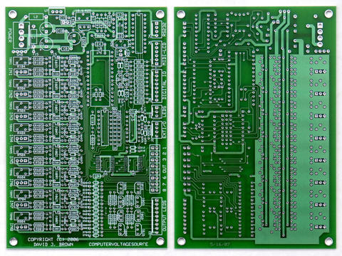
Anyway, back to my lunch exercise.  The LCD_Support PCB has a power
voltage regulator, MIDI, and display functionality.  This board is
available from John Loffink.  My I2C Analog-Digital PCB is available
from ExpressPCB for $20 if you have two friends to buy the extra PCBs.
My sequencer is a program that might be useful to others, especially
as a starting program. So with that in mind, I penciled out a minimum
AtomPro design configuration.

CV outputs adds cost and complexity and takes parts that are in
allocation until late summer.  I assume most people have a MIDI to CV
converter of some kind in order to use a typical keyboard. If you
eliminate the CV outputs and run everything off a single supply you
can eliminate a number of parts and still run a useful program like
the sequencer.

Inputs would be:
1 user control potentiometer
3 user switches (start, stop and reset)
Clock input jack
+5 volts in (from LCD Support PCB)
16 sequencer potentiometers/inputs (from I2C Analog-Digial PCB)

Outputs would be:
MIDI (from LCD Support PCB)
Trigger jack
Gate 1 jack
Gate 2 jack

This configuration would have the same features as my PSIM Sequencer
only without the CV output.  The program would run unmodified except
for one output routine which would be very simple to modify.

Later, multiple DACs could be added by wiring them to the Trigger /
Gate 1 / Gate 2 outputs and using chip selects from the I2C Analog-
Digital PCB.

This design would be a low-cost minimum system with a useable
sequencer application.  A lot of other applications could be run using
MIDI input, output and the switches and controls. Later analog inputs
or analog outputs could be added along with another voltage regulator.

The design is simple enough.  My parts count is 8 diodes, 7 resistors,
2 capacitors, 3 switches, 4 IO jacks, 1 AtomPro, and 1 RS-232
connector. Anyone could lay this out as a first-time project using
ExpressPCB for their mini-board service (3 quicks for $51).  I'd
supply the schematics and program modifications.

Any interest?

Dave


--- In ComputerVoltageSources@yahoogroups.com, "wiardmodular"
<wiardmodular@...> wrote:
> > In retrospect, I would change my design. The 0 to 10 and +/- 5
> > volt input selection is great. I might eliminate the extra 8
> > potentiometers and just have done this selection with switches. I
> > wanted the extra potentiometers for a sequencer which I would do
> > now using I2C.
>
> Why would you use the I2C instead of the 8 0 to 10v and 8 offset
> pots for a 16 step sequencer?  Your original approach seemed quite
> elegant.
>
> Wasn't the first approach faster for response times?  Is the lag
> between turning the pots and the output using I2C noticeable/greater
> than the 0 to 10 +/-5v pots?
>
> Just curious what the drawbacks were to the first approach.
Message
Re: PSIM replacement status?
2007-04-24 by djbrow54
Attachments
- No local attachments were found for this message.