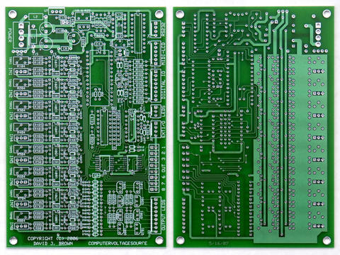
If you are going to use my panel design, I have some suggestions.

Double-check the LCD dimensions. This fit perfect for the display I
used but I don't think it is still available. John's recommended
display should be compatible, but someone should check it out with the
panel.

I chose the Piher potentiometers that use a smaller 7 mm mounting
hole. You'll have to decide what size mounting hole you want.

In the photo of the rear, you'll see that the two MTA connectors on
the LCD_Support PCB are oriented such that the wires to the connector
are to the top. There is limited spacing if you have a cabinet with
the top 1/2" blocked as many wood cabinets do. Alternatives would be
to lower the LCD, use the "thru" connectors so the wires connect on
the opposite side, don't use connectors and solder directly to the
PCB, bend the wires in a tight fashion at the connector, or just
install the MTA connectors backwards. I use mine with rack rails so it
doesn't matter. I personally would leave everything as is and use the
"thru" connectors.

There is no provision for mounting the PCB. I made my own bracket.
Perhaps someone can figure out a better means of mounting.

There is no provision for mounting the 11 LEDs. This would be an
opportunity for someone to do a small PCB. I just soldered LEDs to a
vectorboard and RTV'd it to the panel.

You have to decide if you want the EXT IO connector. I use it all the
time with my PSIM Expansion for an auxilary keypad and control.
However, the PS2 connector I picked is awful. It required front-side
milling to recess the connector (which worked fine but is an extra
cost step), it was a PCB mount with very small pins to solder to, but
the worst is there is no locking mechanism so the mating connector is
easily pulled loose.  There are threads on the end of this connector
but I have not been able to find a mating connector that uses them.
The pins are small and they are a pain to solder. I'd probably change
and use a 4 pin DIN like the Mouser 16HR654 and use the same hole
pattern as for the MIDI connector.

Dave


--- In ComputerVoltageSources@yahoogroups.com, "Doug Wellington"
<DougWellington@...> wrote:
> Is anyone interested in a group buy on the front panel?
> Individually, it will cost $120.73, but for an order of 5-9 that is
> reduced to $108.66 and for 10-19, it's only $96.58.  At some point,
> I'll get around to making a stooge panel for it, but with the
> current list of panels to make, it will probably be several months
> before I'd get to it...
> --
> -Doug
> http://www.analognotes.com
> http://www.stoogepanels.com
> http://www.dougwellington.com
Message
Front Panel
2007-08-02 by djbrow54
Attachments
- No local attachments were found for this message.