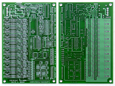
Hi All,
Here is the next installment of my CVS assembly project diary.

At Mr. Brown's suggestion, i stuffed and soldered the CVS PCB in
functional sections. This makes it easy to test in stages and mitigate
the risk of facing a needle-in-a-haystack debugging chore if something
goes amiss. The functional sections conform to the schematic pages. i
simply took a schematic page and stuffed the components found on each
page into the PCB. There are a lot of parts on this board and Mr.
Brown's mnemonic component numbering scheme helped me keep the parts
sorted out. In this scheme (ie) resistors that share a common function
and value will all have similar, rather than sequential numbers. For
instance, all the LED current-limiting resistors are numbered
109,209,309,etc. If you use the BOM to order from mouser, the
components will be packaged separately and i recommend that you write
the schematic designation numbers on the bags before stuffing the
board. This preparation saved me a lot of effort.

i started with schematic page 5, the power section. After soldering, i
could test the 5V buss and set the ref. voltages, with no possibility
of damaging any components 'downstream'. A good thing too! because
this is the one area where i brain-farted and reversed the positions
of the r25 & r26 trimmers. The unsolder was no worse than on any other
through-hole PCB and i got it put right easily. Having the supply
voltages squared-away early gave me some security that i would not be
incinerating the $60 BasicAtom when i tested the next section.

i stuffed the Main Microprocessor section next - page 4 of the
schematic. i'll confess that i'm an 'IC sockets' kind of guy, i
realize that this practice is controversial and i'll only submit that,
in my life, sockets have solved more problems than they've caused but
i'm the first to concede that they can cause problems especially with
high-speed data signals. So i didn't skimp and used very high quality
machine-pin sockets for the CVS. The sockets allowed me to test this
section very carefully in stages. Remember that i already had the
surface-mount converters in place (couldn't do sockets there!) and so
i decided to stuff and solder-in the output/LED section from page 3 of
the schematic at this time too. I recommend that you wire-in your
output and 'start-stop' LED's or ,at least, make a temporary rig of
the 10 LED's at this stage too. This is also the time to assemble and
install the RS232 socket (from page 1 of the panel schematic). Testing
this section can be 'exciting'. With all the LED's in place, i
installed ONLY U5, the BasicAtom (not U4 or U6). i did not connect a
serial cable and then...... i applied power.
The gods smiled; No Smoke!
... and there was a pleasant surprise. The start and stop LED's
flashed in an alternating pattern and the output LED's displayed a
moving pattern as well. Mind you, there was no program in there that
-i- loaded!. There was no serial cable even attached! The origin of
the program that generated this display is still a benign mystery to
me. There is speculation that BasicMicro installs a 'burn-in' program
at the factory that remains resident until the user overwrites it. But
this is unconfirmed. It will be interesting to see what experiences
other users have.
At any rate, i now had reasonable confirmation that my BasicAtom,
converters, and LED's were all happy. At this point it is possible to
connect an RS232 cable and program the BasicAtom with your own
routines to check-out the OUTPUT section. But i decided to install U4
& U6 and continue with the smoke-testing instead. All was well.
Flushed with the relief of not burning up my processor, i charged
ahead and stuffed the first 4 input channels (on page 1 of the
schematic). After soldering this section in, one has an enhanced
equivalent of a PSIM. So i decided that this was the time to hook-up
the RS232 and try pumping some software into the processor. i also
hooked up my LCD submodule at this point.
i'll confess that i hit some snags here, my compiles were not
verifying and transmission was sporadic , i never got serial data
cleanly into the port. But the cause of my grief was solely due to the
fact that my AtomPro software development environment had not been
updated since the lead time on a PSIM was 4 weeks(!) When i updated my
environment to Basic Atom Pro 8.0.1.0 on Windows XP, everything
snapped to attention in short order, and though i pride myself on
being rather stoic about modern 'conveniences' i probably burned up
four hours just blinking the lights and spraying graffiti across that
LCD!!!!
=)
i promise myself to start on more substantive ventures soon though.
Now that i have a platform i'm going to get serious about studying Mr.
Brown's template and adapting it to some serious musical frivolity.
There is more to do , of course, i have to stuff and solder the
remaining input channels (5-8), calibrate the whole enchilada, and set
it up in it's box.
But for such a dense and delicate project, this is a happy ending
indeed folks! i would not call this CVS board a beginners project by
any stretch but , from where i sit, i believe any experienced amateur
could access this luxury with a very modest investment of care and effort.
Kudos to Dave, Grant, John & Harry for getting something real on the
table! (whispers...) maybe the jinx is OVER!

-doc
Message
The "Beta diaries" installment 2; another CVS emerges from the primordial ooze!
2007-09-25 by drmabuce
Attachments
- No local attachments were found for this message.