Photos of my MOTM-101 combined with two Oakley S&H modules
2003-11-28 by Richard Brewster
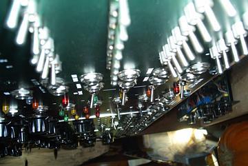
Larry Hendry wrote:

>Well, I do expect to see photos.
>
>
>
>
Ok, they are now uploaded to my files area:

http://groups.yahoo.com/group/motmpanels/files/Richard%20Brewster%20Designs/

There are 4 photos, called MOTM-101R-something.jpg, showing the
construction, front, back, and side views.  This project came out of my
drive to cram more modules into less space.  I wanted more Sample & Hold
modules and Oakley came out recently with a nice little unit.  The
Oakley S&H contains two independent modules: a S&H and a slew.  I've
never cared much for exponential slewing circuits, so by omitting these
and the slewing circuit from the MOTM-101 (and also the random vibratto
from the MOTM-101) I was able to have three S&H circuits together with
the MOTM internal clock and noise source all in a 2U panel.  The panel
itself is a beautiful Stooge design, made to my specifications by Dave
Bradley.

For this mod I made extensive changes to the MOTM circuit board.  I
wanted to have switched clock polarity.  The Oakley boards include a
clock inverter, but the standard Oakley panel has two inputs for the
clock with the non-inverting input just normalled from the output of the
inverter.  Instead, I use a center-off switch to select the clock input
from the panel jack or from the inverter circuit (which is also driven
by the same panel jack).  That way I can even stop the clocking with the
switch placed in the center off position.  I added this feature to the
MOTM by using a spare op amp on the MOTM board as a clock inverter.
Other mods to the MOTM-101:

1.  I made the sample occur on the rising edge of the clock, so that the
clock polarity would be in the same phase as the Oakleys.
2.  I rebuild one of the Oakley slewing modules as a third  isolated
output LED driver.  This drives the third output LED off the MOTM output.
3.  I added an input buffer ahead of the LEVEL pot on the MOTM circuit.
4.  I used the remaining Oakley slewing circut to buffer the output of
the MOTM, set to minimum slew.  This mimics the original MOTM output
design, which had been canabalized for the new input buffer..

One idea didn't work.  I was hoping to have an Analog Shift Register by
normalling the output of S&H 1 into the input of 2, etc., as indicated
by the front panel design.  This works for cascaded MOTM-101 modules and
it would also work for a chain of Oakely modules if the slewing outputs
were used.  The key is that if all three are clocked simultaneously, the
outputs must remain stable for a brief period of time so the next stage
can acquire it before it changes.  This is not the case if the outputs
don't go through a slew limiter.  Since the Oakley outputs don't, they
shift so quickly that the new value is captured by all the units.  But
that's a minor flaw.

I am pleased with the way this came out.  It was a bit of a risk because
I wasn't sure how the panel parts would all fit and indeed it did
require cutting out the bottom corner of the MOTM circuit board to fit
the jack for the WHITE noise output.  I don't expect anybody to
replicate this exact project.  But you may want to consider following
the design of my panel on the left side (the Oakley side) and make a 1U
panel with 2 Oakly S&H modules, if you don't mind omitting the slewing
feature.  If you do this, I recommend still building the slewing circuit
and hard-wiring the output of the S&H through it.  Just short the slew
pot connections, so that you get the minimum slew by default.  This
output structure is like the original MOTM-101 output.  That way you CAN
patch up an ASR and have it work.

-Richard Brewster