--- In cgs_synth@yahoogroups.com, "ed.j.wise" <dustin.sedlacek@g...>
wrote:
jacks. then onto the inputs of 8 pots, the wipers go to the inputs
on
the PCB -
(from Ken's explanation - "There are numerous ways this board can be
used. For example, each input could be fed by a pot wired as a
voltage
divider, with it's input end normalized to +VE via a 1k resistor.
This
way you would be able to use the module as a sequencer when not
using
it as a switch." )
i placed the pots after the jacks so i could also use them to set
the
input levels.
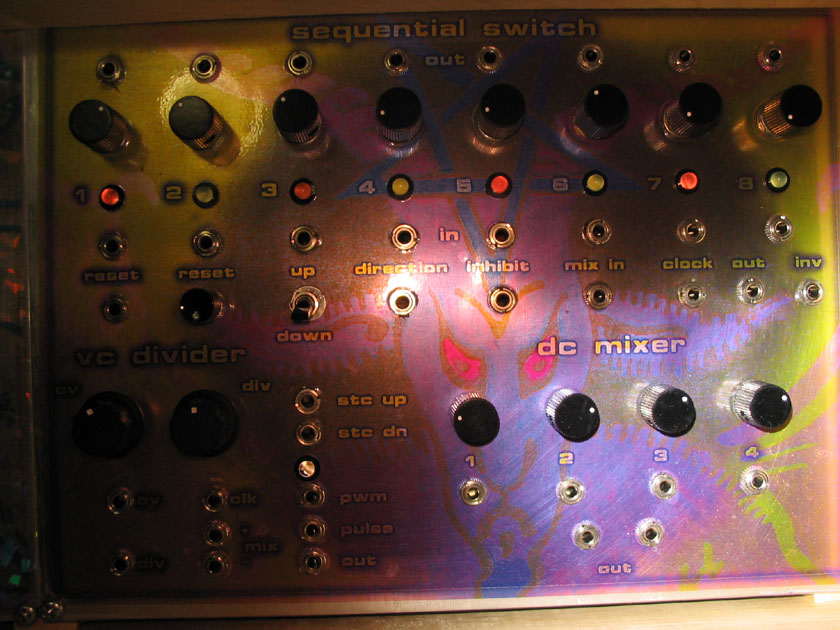
this module makes an excellent sequencer - especially with the
up/down, inhibit and reset controls.
then you can feed cv signals to the inputs and patch the output to a
vco - it gets interesting.
or feed in audio signals for an analog sequential 'sampler'.
a pic of my panel is here -
http://www.sdiy.org/pinky/picture010.jpg
andrew
wrote:
> how do you make a seq switch a sequencer ? i am cloudy on thisanyone
> have some tips or pics ? or other friendly info ?mine has +15V via 1k resistors fed to the switch pins of the 8 input
jacks. then onto the inputs of 8 pots, the wipers go to the inputs
on
the PCB -
(from Ken's explanation - "There are numerous ways this board can be
used. For example, each input could be fed by a pot wired as a
voltage
divider, with it's input end normalized to +VE via a 1k resistor.
This
way you would be able to use the module as a sequencer when not
using
it as a switch." )
i placed the pots after the jacks so i could also use them to set
the
input levels.
this module makes an excellent sequencer - especially with the
up/down, inhibit and reset controls.
then you can feed cv signals to the inputs and patch the output to a
vco - it gets interesting.
or feed in audio signals for an analog sequential 'sampler'.
a pic of my panel is here -
http://www.sdiy.org/pinky/picture010.jpg
andrew