|
Breadboarding technique for fine pitch SMD parts:
I am interested in prototyping techniques that other people use. I am always trying out different ways of breadboarding and prototyping circuits. Here is my contribution. I have recently come up with a way of using SMD (surface mount device) parts in prototype designs. The problem that I always have is soldering wires to SMD IC's so that I could make connections to the other components. The SMD devices that I use have a pitch (pin spacing) of 1.27mm (0.05in.) to 0.65mm (0.025in.). Through hole devices usually have a 2.54mm (0.1in.) pitch. You can buy adapters (surfboards) and such but I never have the right one or they are too expensive to use for simple home built projects. So here is the method I've been using; I like to call it kindergarten engineering because of the materials used. Start by stripping the ends from pieces of 30 gauge wire wrap wire. I use pieces about 5in. long with 1in. stripped (the ends are trimmed later). Use good strippers or use the slot type strippers designed for wire wrap wire. Don't nick the wire. Cut as many pieces as there are pins on the device. Ok, you have the wires and you have the device, the problem is getting the wires on the device. Soldering them individually is a pain and is not worth the effort to even try it on fine pitch devices. If you could perfectly align the wires and hold them all down it would be a lot easier to solder them. Aligning the wires is easy, just use a computer drawing program and draw lines that are as far apart as the pins on the device. Any drawing program will work but be sure and place the device on the printout to see if the lines match pin spacing. But the wires won't stick to the lines on the paper.
Here's the kindergarten part, GLUE STICK. This is not hot glue, this is the Uhu non toxic glue stick for paper. Smear glue stick over the lines you have printed and then lay half the wires down in it. Align the wires on top of the lines with a tweezer. A 10x magnifier really helps. Only the bare part needs to be perfectly aligned. Make sure that the edges of the insulation are aligned straight and perpendicular to the wires. The working time of the glue stick is long enough that I was able to align the wires in plenty of time before it dried. Now take a strip of paper and smear glue stick on it and paste it on top of the insulated part of the wires. This is just to hold them tight so they won't move when you solder the device to the wires. Paste another strip over the bare part so that there is just a little bit of wire showing.
Now you have many wires perfectly lined up with the same spacing as the IC pins. The bare ends are sticking out and are held down in a thin layer of glue stick. You are ready to solder half the wires to one side of the device. Use your favorite soldering technique for surface mount parts and solder the part just like it is on a PCB. Note that the paper and glue stick will not melt. Do not use tape it will melt. You might have some trouble if you are not experienced in soldering SMD parts.
Now the part is soldered. How do you get all the paper and glue stick off? Use very hot water (hot enough for tea or coco) and soak the pieces. The glue stick is water soluble and will come off completely without any chemicals. Use a very sharp razor blade and trim bare ends of the wires so they don't stick all the way across the device. Repeat for the other side of the device. Heat some extra water and have some tea or coco when you are done, you'll need it.
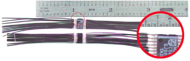
The technique takes some practice and experience working with SMD parts but its the only way I know of using SMD parts reliably in prototype designs. I was able to attach 20 wires to a 0.025in. pitch device in about 20 minutes using this technique and a good magnifier. Let me know if you come up with any improvements.
manifold_1@yahoo.com; June, 2000 |