Databases
Yahoo database tables
These records come from the Yahoo Groups databases export preserved for this archive.
-
CVS FAQ
· 19 records · 3 columns · Owner djbrow54 · Updated 2010-10-11
CVS Module and PCB information
-
LCD_Support FAQ
· 12 records · 3 columns · Owner djbrow54 · Updated 2008-02-03
LCD_Support Module and PCB Information
Database table
CVS FAQ
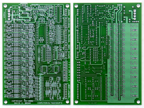
CVS Module and PCB information
19 records · Owner djbrow54 · Created 2007-09-08 · Updated 2010-10-11
| Record | Tip | Description | Author |
|---|---|---|---|
| 2 | IC orientation | The SMT DACs U2 and U2 are oriented opposite from the DIP parts. All DIP parts have pin 1 towards the top of the PCB. The SMT parts have pin 1 towards the bottom of the PCB. The solder mask shows the correct orientation. | Dave Brown |
| 3 | Transistor orientation | Transistors Q101 – Q801 are not all oriented the same direction. Q301, Q401, Q701, and Q801 are oriented opposite from Q101, Q201, Q501, and Q601. | Dave Brown |
| 4 | R32 and R33 resistors | R32 and R33 limit current for I2C over/under voltage. 1/8 watt resistors were used for board space requirements. 1/4 watt resistors may be used if mounted radially. Values may be changed depending on application. | Dave Brown |
| 5 | R30 and R31 resistors | R30 and R31 limit current if the AtomPro P4 and P5 are set to outputs. 1/8 watt resistors were used for board space requirements and were placed inside the U5 socket footprint. The socket footprint must allow room for these components. The resistors may also be installed on the bottom side of the PCB or simply replaced with jumper wires. | Dave Brown |
| 6 | +5 volt operation | JP1 is pre-connected on the top layer of the PCB and does not need to be installed. If a separate +5 volt supply is desired, cut the trace on the top layer between the two pins and connect pin 2 of JP1 to +5 volts. | Dave Brown |
| 7 | J6 connection to LCD_Support | The layout of J6 is reversed to match the layout of J5 on the LCD_Support PCB (pin 1 of J6 is on the opposite end). | Dave Brown |
| 8 | Reset current limit | R8 is very important to install. The AtomPro28 has an active power-on-reset circuit and grounding the reset pin shorts the output of this circuit. R8 limits the short circuit current. (Update 10-10-10: The AtomPro28 reset circuit has been changed to a to a passive capacitor/diode/resistor similar to the AtomPro24.) | Dave Brown |
| 9 | Protection diodes | The 39 over/under voltage protection diodes (D5 - D804) are schottky and chosen for low leakage and a forward voltage drop of ~0.3 volts to meet the over/under voltage specification of the Renesas H8/3664 processor. Other diodes with similar specifications may be used. | Dave Brown |
| 10 | Input filters | C106, C206, C306, C406, C506, C606, C706, and C806 on the schematic are not recommended for installation and are not included on the PCB. These capacitors reduce input noise but also increase input slew rate and degrade input step response. Optional use depends upon application and performance requirements. | Dave Brown |
| 11 | R25 and R26 adjustment | Adjust R25 to calibrate the 10.666 volts as measured at the end of R23 closest to U8. Then adjust R26 to calibrate the 10.000 volts as measured at pin 9 of U9. Check pin 12 of U9 to be close to 5.0 volts. | Dave Brown |
| 12 | Input trimmer adjustment | The input trimmers R104, R204, R304, R404, R504, R604, R704 and R804 are adjusted with a calibration program that displays the digital value of the analog inputs. The trimmers are adjusted to a value of 1023 with the 10.0 reference or other precision voltage source connected to the inputs. Note that this adjustment also compensates for the tolerance range of the +5 volt regulator U7 and overall gain will not be exactly 0.5X. | Dave Brown |
| 13 | Eliminating reference voltages | The programmable reference voltages may be eliminated by not installing R26, R27, R28, C12, C13, C16, C17, U9, U10, and J11. | Dave Brown |
| 14 | Fixed reference voltages | Fixed (non-programmable) +10 and +5 reference voltages may be generated by not installing U9 and connecting pin 8 to 9 and pin 3 to 12 on U9. | Dave Brown |
| 15 | Four channel configuration | A four channel version may be built by deleting the additional 4 input and output parts. If the programmable reference voltages are not used, then those parts along with U6 and associated parts may be deleted. RN1 should be installed or a resistor installed between pin 1 and 3 so that pin 1 of U4 will be pulled high to enable the U2 chip select. | Dave Brown |
| 16 | Additional digital inputs / outputs | There are 3 unused digital inputs / outputs on U6 that connect to pins 3-5 on J9. These have resistor pullups so you can connect three switches to ground for additional inputs. You can also use these for outputs or panel inputs but be sure to add appropriate over / under voltage protection. For additional digital inputs / outputs, an additional MCP23008 can be interfaced directly to J5. You use the I2CIN / I2COUT commands to read / write these bits. There is reference information in the Hardware > I2C Analog-Digital folder. | Dave Brown |
| 17 | SMT soldering | Here's how I solder the SMT DACs: First, use a very fine point tip (photo in the "Files > Hardware > CVS Module" folder). Then align the DAC on the PCB and use a piece of masking tape to hold it in place. The part needs to be aligned in both directions (horizontal and vertical). Use a magnifying glass to really see where it is placed. Then use fine solder and solder one corner pin. Remove the masking tape and solder the opposite corner pin. There is a bit of compliance in the pins so you can adjust the DAC to align the pin dead center on the pad. Then reflow the first pin and adjust the DAC to align that pin dead center on the pad. Now use the magnifier to check the alignment on all 16 pins. Solder each pin using fine solder. Then recheck each pin with a magnifier to make sure the solder flowed. If you have a bridge you can remove the excess solder with solder wick. | Dave Brown |
| 18 | AtomPro28 pin 1 orientation | There isn't a marking on the AtomPro28 for pin 1. There is a half circle in copper that marks the top similar to the indentation at the top of an IC. Pin 1 is to the left and pin 28 is to the right of the half circle. The resonator is at the bottom and can be identified as a gray rectangle with two black stripes. If you look carefully you can see 16.0M written on it indicating the frequency. Pin 14 is to the left and pin 15 is to the right of the resonator. | Dave Brown |
| 19 | ATOMPro Info | You can buy the ATOMPro processor from www.basicmicro.com for $59.95. P/N B0204. The software is BasicATOMPRO Software version 8.0.1.0 | Scott Deyo |
| 20 | USB Serial Adapter | Some USB to Serial adapters are not compatible with the AtomPro. The IOGEAR GUC232A adapter is compatible with the AtomPro processor with Windows XP. | Dave Brown |