I have uploaded into the Files>Hardware section my set of schematics.
I did not post these previously because I did not originally generate
them.  I only took other's ideas and draft schematics and enhanced
them with ideas from this group and some of my own. I believe everyone
is in agreement that they should be posted now.  I would like to thank
Grant Richter, Harry Bissell, John Loffink and others who have posted
comments and made input.  I also want to thank John Loffink for his
contributions to the LCD_Support module.

I originally built all portions of these schematics to validate them.
I purchased an AtomPro28 to evaluate and understand it since
BasicMicro still has not released a datasheet.  I also purchased many
of the parts to prototype and validate functionality such as the I2C
interface.  I also purchased a front panel to verify the LCD_Support
module mounting.

Like many of you, I wanted an advanced module and decided the only way
to get one was to build it myself. Since I already has well over $200
invested, I decided to complet a PCB design over Christmas and built
it last month. I have written a 16 step sequencer program (1762 source
lines) that uses 75% of the program memory. I have spent hours with a
scope and protocol analyzer determining how the I2C and serial ports
really work.  Details of my module are documented on my web site at
http://modularsynthesis.com/cvs/cvs.htm

Having completed my module, I am now on to other projects. One of the
many is a remote I2C interface with a keypad and additional controls
for improved user interface.  There are several videos on my website.
I would suggest you view the videos of the LCD display. It adds
awesome capabilities to the module and is why I am now designing a
better user interface.

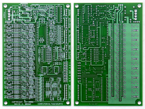
My PCB is not for sale. I designed a 4x6" PCB with a ground plane and
SMT components. There are over 50 wires to the front panel and another
50+ wires on the front panel. The ground plane clearance is 0.012
inches. The PCB is very difficult to solder and once all the wires are
connected it is nearly impossible to access for troubleshooting.

I would, however, be happy to offer suggestions to anyone who wants to
carry forward a PCB design that is more reasonable to build.  Here is
my initial list of suggestions:

1. Decide on a group consensus for the feature set. This particular
set of features cost over $500 in parts alone.

2. Decide on a panel and do a PCB for the jacks and controls.
Soldering over 100 wires was not fun nor practical for may DIY'ers.

3. Decide on an appropriate DAC. I chose the DAC7715U since it was
less expensive than the DAC8420 with a savings of ~$40.00.  This DAC
is in shortage and distributors are not expected to have parts until
after August 2007.  You may also find that stock has been depleted on
the DAC8420 as well. You probably want to use the DAC8420 so you can
get it in the DIP package. Laying out dual package styles is not
really feasible.

4. The LED drivers are simple current sinks and I used amber LEDs.
Basically they are on, dim, or off so they only tell you that an
output is doing something. This portion of the design could be
improved.

5. My power supply noise comes right through into the input buffers
when viewed on a scope. I can see digital ambiguity of +/- 1 count on
my A/D conversions. This could be due to the noise, the inexpensive
potentiometers, or the accuracy of the H8/3664 processor.  I can't
troubleshoot it any further because I can't access my board (due to
all the wires). You might consider adding 12 volt regulators for the
op amps. I adapted my software to input average the A/D conversions
over the last four cycles and is reasonably stable.

6. The display module is a must-have (watch the videos). The I2C works
very well. The hardware interrupt serial support works very well for
MIDI. Having programmable MIDI capability enables a whole new set of
features and having serial communications enables synchronizing
multiple modules (there is a video of this as well).

7. Standardize on a design that has software compatibility. The
advantage of a group design is the ability to build upon other's
software contributions. Anyone wanting a 1 to 16 step sequencer has my
application as a starting point.

8. Use my analog input layout for a starting point. I compressed the
circuit as small as possible with standard power buses so I could step
and repeat this for all the channels.

Best of luck to anyone who volunteers to complete the design of a PCB.
I suggest you be the final "voice" in determining the feature set.

Dave
Message
Schematics posted
2007-02-06 by djbrow54
Attachments
- No local attachments were found for this message.