Finding Clock frequency of my OBXa
2015-02-23 by richtrix@...
Yahoo Groups archive
Index last updated: 2026-04-28 23:39 UTC
Thread
2015-02-23 by richtrix@...
Random question. Anyone know what pins on which component I can find the main clock source for the whole unit? I have access to an oscilloscope to read it with just don't know where to look. I know it will probably be on the main processor on the UCB though. Mine is a late model OBXa and suspect the clock may be a different speed than earlier units.
Most Sincerely,
Rich Clarke
2015-02-23 by Florian Anwander
Hello Rich,

What do you mean with "main clock source"? There are various clocks in a
synth like the OBXa. In a first look I find at least two generators  in
sheet 1 of 3 for Upper Control Board in the service manual Rev. 3.  One
of them is the normal CPU clock, the other drives the !INT, which is
assumingly the mainclock for the S&H stages.

Mux/Demux systems for modulation amounts run quite often on clocks,
which run independent from the CV-to-S&H-Demux clocking (I'm not sure
the OB-Xa uses such a concept anywhere).

Florian

Am 23.02.2015 um 08:55 schrieb richtrix@... [oberheim]:
>
> Random question. Anyone know what pins on which component I can find
> the main clock source for the whole unit? I have access to an
> oscilloscope to read it with just don't know where to look. I know it
> will probably be on the main processor on the UCB though. Mine is a
> late model OBXa and suspect the clock may be a different speed than
> earlier units.
>
>
>
> Most Sincerely,
>
> Rich Clarke
>
>
2015-02-23 by Bob Grieb
Hi,
     I am guessing that you are curious about the clock frequency of the main
controlling CPU, which would be the Z80 (A101 on the upper control board)I checked both Rev 1 and Rev 3 schematics and in both cases the main crystaloscillator was 4.9152 MHz.   That signal is divided by two and then fed to the Z80.Since it's not a Z80A (4 MHz limit) but a plain Z80, the clock limit was 2.5 MHz,so they would have been just under that.
    The main clock frequency is divided down by other circuits to generate interruptrates, rates for updating the voices, and clocks for serial communication (MIDI).Changing the main clock is not as simple as it might sound as all of those derived ones
change too, and that hardware was designed to work properly with those speeds in mind.If you speed up the main clock and put in a faster CPU that can handle it, the CPU maybe OK, but the RAM's and EPROMs may not be fast enough and some of the other
hw may become flaky as well.
    You can see  the main CPU clock on pin 6 of the Z80.  Be careful not to short thatpin to pin 5 or pin 7 when you are probing.

Bob From: "richtrix@... [oberheim]" <oberheim@yahoogroups.com>
To: oberheim@yahoogroups.com
Sent: Monday, February 23, 2015 2:55 AM
Subject: [oberheim] Finding Clock frequency of my OBXa
<!--#yiv8322407558 #yiv8322407558 .yiv8322407558ygrp-photo-title{clear:both;font-size:smaller;height:15px;overflow:hidden;text-align:center;width:75px;}#yiv8322407558 div.yiv8322407558ygrp-photo{background-position:center;background-repeat:no-repeat;background-color:white;border:1px solid black;height:62px;width:62px;}#yiv8322407558 div.yiv8322407558photo-title a, #yiv8322407558 div.yiv8322407558photo-title a:active, #yiv8322407558 div.yiv8322407558photo-title a:hover, #yiv8322407558 div.yiv8322407558photo-title a:visited {text-decoration:none;}#yiv8322407558 div.yiv8322407558attach-table div.yiv8322407558attach-row {clear:both;}#yiv8322407558 div.yiv8322407558attach-table div.yiv8322407558attach-row div {float:left;}#yiv8322407558 p {clear:both;padding:15px 0 3px 0;overflow:hidden;}#yiv8322407558 div.yiv8322407558ygrp-file {width:30px;}#yiv8322407558 div.yiv8322407558attach-table div.yiv8322407558attach-row div div a {text-decoration:none;}#yiv8322407558 div.yiv8322407558attach-table div.yiv8322407558attach-row div div span {font-weight:normal;}#yiv8322407558 div.yiv8322407558ygrp-file-title {font-weight:bold;}#yiv8322407558 --> <!--#yiv8322407558 #yiv8322407558ygrp-mkp {border:1px solid #d8d8d8;font-family:Arial;margin:10px 0;padding:0 10px;}#yiv8322407558 #yiv8322407558ygrp-mkp hr {border:1px solid #d8d8d8;}#yiv8322407558 #yiv8322407558ygrp-mkp #yiv8322407558hd {color:#628c2a;font-size:85%;font-weight:700;line-height:122%;margin:10px 0;}#yiv8322407558 #yiv8322407558ygrp-mkp #yiv8322407558ads {margin-bottom:10px;}#yiv8322407558 #yiv8322407558ygrp-mkp .yiv8322407558ad {padding:0 0;}#yiv8322407558 #yiv8322407558ygrp-mkp .yiv8322407558ad p {margin:0;}#yiv8322407558 #yiv8322407558ygrp-mkp .yiv8322407558ad a {color:#0000ff;text-decoration:none;}-->
Random question. Anyone know what pins on which component I can find the main clock source for the whole unit? I have access to an oscilloscope to read it with just don't know where to look. I know it will probably be on the main processor on the UCB though. Mine is a late model OBXa and suspect the clock may be a different speed than earlier units.
Most Sincerely,Rich Clarke2015-02-25 by richtrix@...
2015-02-25 by Bob Grieb
If the popping noise is only on specific voices, then it should be related to
the control voltages that the CPU is writing out for pitch, cutoff, etc.The Z80 writes these over and over, something like 50-100 times each
second or so.   If every so often the wrong value was written out, you wouldhear a momentary pop of some kind.   Does this only happen when MIDI
data is being received by the CPU?   It could be a bug in his code, if so.If he is clocking the CPU faster than the original design, that could causereliability problems, since the circuits were all design with a specific operatingfrequency in mind.  Some chips may not propagate the information fast enoughto run at higher clock rates.   I am not familiar with the Encore MIDI kit,
so I can't say how it was designed.  It could also be an issue with the S&H
analog circuits not working just right at the higher frequency.   There may
be a decoder that only affects voices 5-8.    Good luck.
      From: "richtrix@... [oberheim]" <oberheim@yahoogroups.com>
 To: oberheim@yahoogroups.com
 Sent: Wednesday, February 25, 2015 1:54 AM
 Subject: Re: [oberheim] Finding Clock frequency of my OBXa [1 Attachment]
2015-02-25 by Bob Grieb
This page is here to provide you with information to troubleshoot OBXaMK installation issues. Over the years, we have discovered certain problems that fall into a few specific categories.  Autotune trouble
  The autotune hardware changed during the production life of the OBXa. If you find the OBXa refuses to autotune right after installing the MIDI kit, we have a possible solution. Hold down the AUTO button while turning on the power. This will change a mode in the firmware. If this works, you never have to think about it again. You can do this multiple times, but it repeats after 4 attempts. If none of these modes work, contact us...you might have a revision we haven't seen yet.

  Glitchy audio or dropped voices
  This comes from a variety of problems. The fundamental issue is that the OBXa originally ran at 2.5MHz, while the OBXaMK runs at 4MHz. We have helped several customers debug these issues, and this is now documented here to help your troubleshooting efforts.

 One problem is incorrect parts used during repairs over the last 35+ years. Digital logic comes in many varieties, and speed is an important parameter. With stock hardware, an improper substitution may work fine. It only becomes evident when the system is running faster, as is the case when the OBXaMK is installed. We have seen U128 (a 7442) replaced with a 74C42, and that appeared to break the instrument after the MIDI kit was installed.
 We have also seen U160 (a 7442) replaced with a 74C42, and that also appeared to break the instrument after the MIDI kit was installed. We cannot magically know what was done to your instrument before you purchased our kit, so you need to look for things like this. Later models were often not socketed, and it's a dead giveaway if you find one socketed part. This part should be checked against the schematic to insure it is correct.

 In other cases, it's simply a matter of timing tolerance that causes problems. We have recongnized a group of parts that tend to cause this trouble. These problems often will show up as killing 4 voices at once. Either the lower 4 or the upper 4. That is a sure sign you have a timing problem. The parts to suspect are:
U142: 74C174
U143: 74C42
U38: 74C174
U39: 74C42
All of these parts should be replaced with LS or HC or HCT equivalents. These parts are still pretty easy to find online in small quantities.


 If you don't want to replace those parts, another possible solution is to slow down the clock. In 2014, we have allowed the MIDI kit to generate a 3.2MHz clock which seems to alleviate the glitchy behavior. However, this requires you pull the CPU from the socket, lift pin 6 (the clock pin), and solder a small wire to the pad near the Xilinx part as shown. Remember, the stock OBXa runs at 2.5MHz, and running the clock as fast as possible will help MIDI response. So the best solution would be to replace the slower parts on the boards, but this wire mod should also work ok.


Encore Electronics


|   |
|   |  |   |   |   |   |   |
| Encore ElectronicsThis comes from a variety of problems. The fundamental issue is that the OBXa originally ran at 2.5MHz, while the OBXaMK runs at 4MHz.  |
|  |
| View on www.encoreelectroni... | Preview by Yahoo |
|  |
|   |
      From: "richtrix@... [oberheim]" <oberheim@yahoogroups.com>
 To: oberheim@yahoogroups.com
 Sent: Wednesday, February 25, 2015 1:54 AM
 Subject: Re: [oberheim] Finding Clock frequency of my OBXa [1 Attachment]
2015-03-07 by richtrix@...
2015-03-07 by Bob Grieb
Sounds like the patch storage RAM is not working somehow.  Could be an
address line , a data line, or possibly a bad RAM chip.   Probably an easierway to find the frequency of the clk is to simply locate the crystal.   Thefrequency is usually stamped into it.  There is probably only one crystal,and it should be pretty close to the Z80.   The Z80 clock should be half of
that rate.
You can try removing any chips that are socketed having to do with the
patch RAM and then plugging them in again.   Actually, you can just pry
one end up maybe 1/8" or less with a small screwdriver, then push back
down again, then do the other end.   Just a little motion relative to the
socket tends to clean the leads, in case they aren't making good contact.Ground yourself by touching the metal inside the case before doing thisso you don't make a spark from static/ESD.
   Bob
      From: "richtrix@... [oberheim]" <oberheim@yahoogroups.com>
 To: oberheim@yahoogroups.com
 Sent: Saturday, March 7, 2015 1:13 AM
 Subject: Re: [oberheim] Finding Clock frequency of my OBXa
2015-03-19 by richtrix@...
2015-03-19 by Bob Grieb
Hi Rich,
    There are many CMOS chips in this synth.   On my schem, U164 is a 6116 SRAM chip.I don't know exactly how the MIDI kit is set up, or what parts it wants on the MB, so it's toughto answer your question. But assuming that it has its own SRAM and EPROM, then probablyit wouldn't be using U164.   Removing that chip would reduce the load on the data and addressbuses.   There may be a timing problem that is fixed by leaving it in place.   Every so often
the wrong data is latched somewhere when the right (wrong) conditions happen.   If you want to
try to learn more, assuming that RAM chip is not used, you can bend out data and address linesindividually and maybe find out which ones are helping to solve the problem.  But it may be more
than one.   Also, you can only bend the pins so many times before they break.  Your scope probecan also be used to add capacitance to a signal.   You can remove that chip, and then try probing the
pins of the socket one by one.  If it's just one signal that is making the difference, you might find
it that way as well.
    If you do leave that SRAM chip installed, check with your scope to make sure it is not
being selected.   Trigger the scope on the high to low edge of chip select and you should not seeit triggering.
BobFrom: "richtrix@... [oberheim]" <oberheim@yahoogroups.com> To: oberheim@yahoogroups.com Sent: Thursday, March 19, 2015 6:25 PM Subject: Re: [oberheim] Finding Clock frequency of my OBXa
2015-03-19 by Bob Grieb
To save time, bend out all 8 data bus lines, and install U164 with no data busconnections. Then bend out all of the address too if it still is fixing the issue.If that breaks things again, bend back half of the address lines.Then try the other half. Sort of a binary search instead of bending in and out pins one at a time, which could take a lot longer. Always keep the power and gnd to this chip connected. Also, the chip select pin should be connected as well. Assuming the chip is not actuallybeing used, disconnecting address or data lines should be OK. But not the power pins or the chip select/ chip enable pin. Bob
      From: "richtrix@... [oberheim]" <oberheim@yahoogroups.com>
 To: oberheim@yahoogroups.com
 Sent: Thursday, March 19, 2015 6:25 PM
 Subject: Re: [oberheim] Finding Clock frequency of my OBXa
2015-03-21 by richtrix@...
2015-03-21 by Bob Grieb
2015-03-21 by Martin Ator
Does the circuit board use one of the through holes of the socketed chip to make a transistion from the bottom to the top of the board for a power /gnd carrying pcb trace, maybe a power through hole is damaged/intermittent or maybe the extra loading offered by the sram on the supply is just enough to make a faulty diode or other component work properly nearby. It doesn't really make any sense that it works just by having a chip in the socket with its data and addressing lines floating even.


     On Saturday, 21 March 2015, 3:41, "Bob Grieb bobgrieb@... [oberheim]" <oberheim@yahoogroups.com> wrote:


I agree, but that doesn't stop it from happening...From: "richtrix@... [oberheim]" <oberheim@yahoogroups.com> To: oberheim@yahoogroups.com Sent: Friday, March 20, 2015 10:20 PM Subject: Re: [oberheim] Finding Clock frequency of my OBXa Well I lifted all data pins and all address pins and it is still smooth! So now I will just play with it and see if there are any other strange bugs but with U164 neutered I am hoping there won't be any issues. Thanks for that advice Bob. I'll keep you posted. I did finally hear back from Tony Karavidas, the Midi Kit designer, and he so far has only said that this fix makes absolutely zero sense lol. Sincerely,Rich Clarke
2015-03-21 by richtrix@...
2015-03-21 by Bob Grieb
Do you get the blips when just holding one or more keys down?Or does it only make that sound right as you are pressing or releasing a key?
What voltage do you measure at +5MEM? (on U164 pin 24)

If you have all of the data lines for U164 isolated from the bus, then there arethree more pins you can experiment with, trying to see which one affectsthe blips.  Leave the address and data pins bent out and isolated.

Chip enable (18)
Output Enable (20)
Write enable (21)
If you can figure out the exact signal that makes a difference, maybe wecan get a little further.  It should be one of these three.   Leave the power and
gnd pins connected.   If you find the signal that makes the difference, then removeU164 and connect a 22pf, 33pf, or 47 pf cap to gnd from that signal as an experiment.You can just stick the leads into the socket temporarily.
You should get a similar effect.   Of course it may take more than one of those signalsto cause the blips.
Bob
      From: "richtrix@... [oberheim]" <oberheim@yahoogroups.com>
 To: oberheim@yahoogroups.com
 Sent: Saturday, March 21, 2015 9:09 AM
 Subject: Re: [oberheim] Finding Clock frequency of my OBXa [2 Attachments]
2015-03-22 by richtrix@...
2015-03-22 by Bob Grieb
In the video, over at the left edge the scope seems to be showing a
dip in the +5MEM supply.    That supply is created by ORing the 5V digital
supply and the battery, so there will be a diode drop in it.   But that should be
constant, not a dip like we seem to be seeing.   Maybe you shouldscope both of your 5V supplies more carefully.   Can you put the scope on 1V/div,or maybe even 0.5V/div, and set it up to trigger on a negative edge at 4.75V or
something?  Then  if it triggers, move the trigger point and the glitch to the centerof the scope so you can see it clearly.   If the power supply is drooping too much,that cause cause lots of strange things to happen.   There are two 5V supplies.I would check them both.  You might want to check the other supplies while you
are at it.  You can use the AC coupled setting of your scope to see 15V suppliesat 0.5V / div.   In that case you are not measuring the voltage, just looking
for noise and dips.

    Did you replace the power transistor in the supply with the exact type usedoriginally?   Any other P/S parts replaced?
BobFrom: "richtrix@... [oberheim]" <oberheim@yahoogroups.com> To: oberheim@yahoogroups.com Sent: Sunday, March 22, 2015 8:51 AM Subject: Re: [oberheim] Finding Clock frequency of my OBXa [2 Attachments]
2015-03-22 by Peter Mörck
In the video, over at the left edge the scope seems to be showing adip in the +5MEM supply. That supply is created by ORing the 5V digitalsupply and the battery, so there will be a diode drop in it. But that should beconstant, not a dip like we seem to be seeing. Maybe you shouldscope both of your 5V supplies more carefully. Can you put the scope on 1V/div,or maybe even 0.5V/div, and set it up to trigger on a negative edge at 4.75V orsomething? Then if it triggers, move the trigger point and the glitch to the centerof the scope so you can see it clearly. If the power supply is drooping too much,that cause cause lots of strange things to happen. There are two 5V supplies.I would check them both. You might want to check the other supplies while youare at it. You can use the AC coupled setting of your scope to see 15V suppliesat 0.5V / div. In that case you are not measuring the voltage, just lookingfor noise and dips.Did you replace the power transistor in the supply with the exact type usedoriginally? Any other P/S parts replaced?Bob
      From: "richtrix@... [oberheim]" <oberheim@yahoogroups.com>
 To: oberheim@yahoogroups.com
 Sent: Sunday, March 22, 2015 8:51 AM
 Subject: Re: [oberheim] Finding Clock frequency of my OBXa [2 Attachments]
[Attachment(s) from richtrix@... [oberheim] included below]
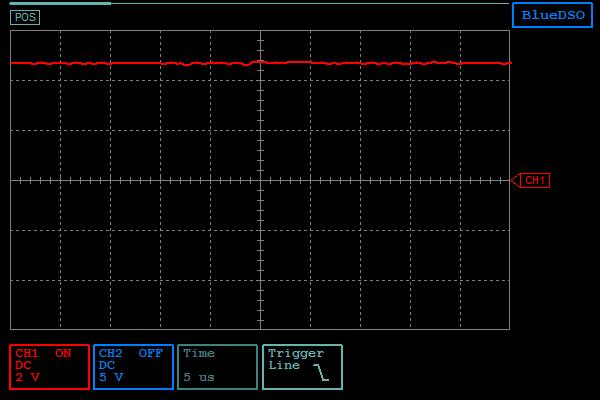
Hi again Bob,The blips happen at all phases of keypress. They are seemingly random and occur so long as 5-8 are making any kind of sound (attack, sustain, decay).I measured the 5V pin with my little digital scope and it was seemingly pretty clean as seen in the attached image. Then I tightened the time frame and that revealed some artifacts (see attached video)I'm not hugely trusting this scope when it comes to correct ranging and proper voltage measurement but the video is probably what is happening in reality. The probes were hard mounted and not shifting.So something may be wrong with my +5 V supply. This in not my first PSU problem if so. I had to replace one of the power transistors when I got the OBXa.I will try bending out those different pins on U164 Monday.
2015-03-24 by richtrix@...
2015-04-22 by richtrix@...
2015-04-23 by Bob Grieb
Hi Rich,    I seem to have deleted the old emails.  Just to confirm, you have a later(rev 3 schems) Xa?   And we were talking about U164, right?   Now you
are saying that only the gnd and +5MEM pins are connected.  Is that correct?The 47 pf cap suggestion was testing delay sensitivity for one of the digitalconnections to that chip, not the power supply.   If only connecting the supplypins makes a difference, then it's a different sort of problem.  On the supply pin,you can use 0.1 uF instead of 47 pf.   Also, +VMEM should already have two capsto gnd, C4 and C5.   Maybe C4 is bad?  Sounds like you need to scope +VMEM.
BobFrom: "richtrix@... [oberheim]" <oberheim@yahoogroups.com> To: oberheim@yahoogroups.com Sent: Wednesday, April 22, 2015 12:25 AM Subject: [oberheim] Re: Finding Clock frequency of my OBXa
2015-04-24 by richtrix@...
2015-05-05 by richtrix@...