Hi Nat,
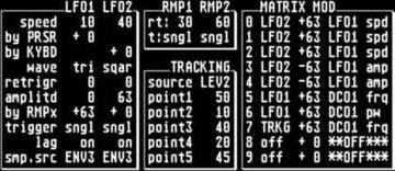
The power comes in from the AC adapter socket and feeds L4 for the ground side and L3 for the +9 volts when the switch is on. L3 and L4 are inductors and the power should be the same going in and coming out. Then the power goes to pin 1 of the 5 volt regulator. The center leg of the voltage regulator should be ground. The right leg of the regulator (pin 3) viewed from the top of the board should be 5 volts DC. sometimes the boards crack or a trace gets burnt through. Look closely with a magnifier if need be.
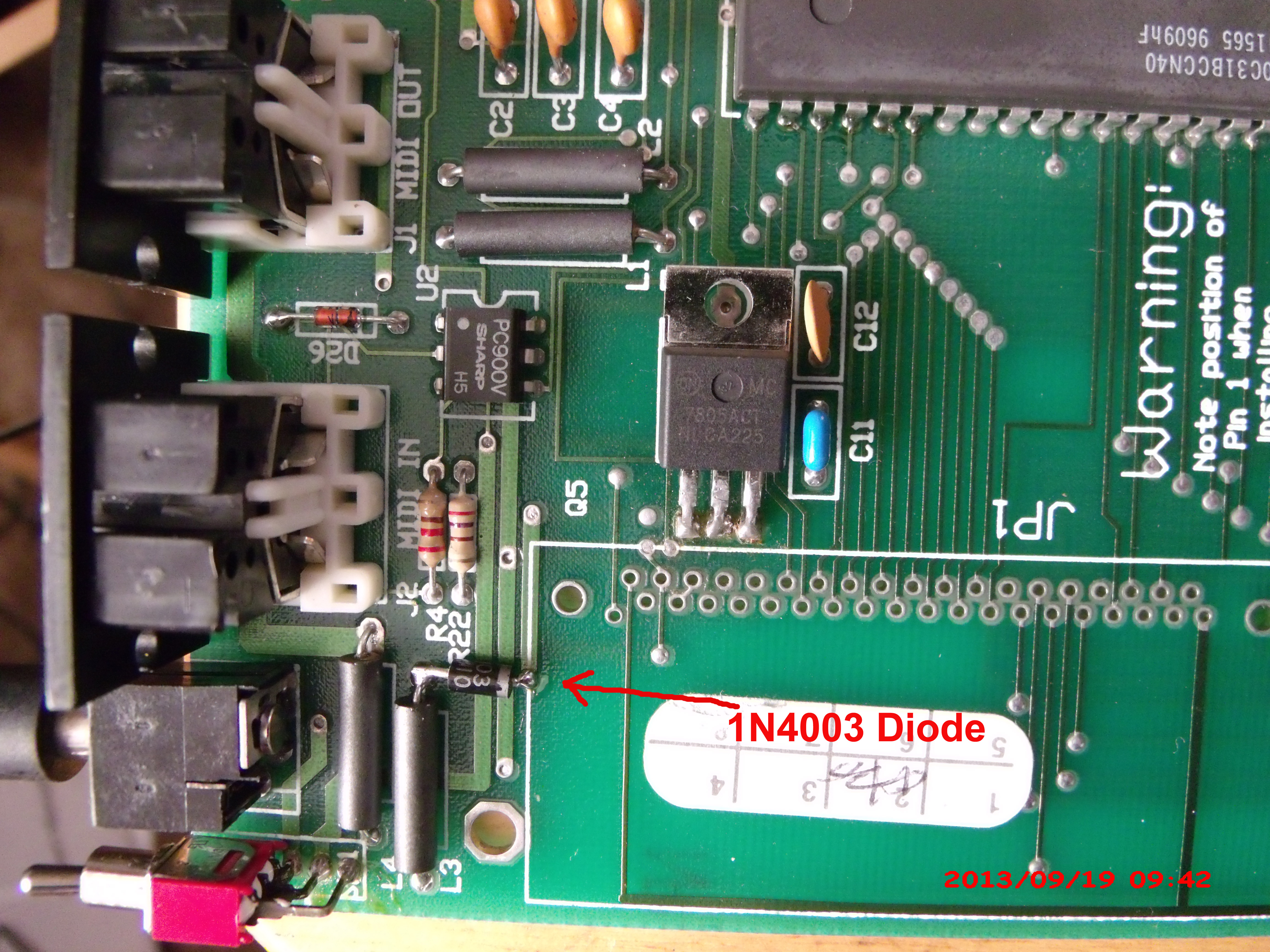
I attached some pics but I'm not sure they will come through. These pics are in the photos area here in the group. Ignore the diode and the cut trace. This is an input power mod I installed in a friends unit. This mod protects against the wrong AC adapter being used. The pics show enough detail so we can discuss you power problems. If you can't fix these units you can send them one at a time to me and I will fix them if it is possible. Are you in the states? I'm in upstate New York. I don't charge much and I have references..... Plus there is a mod to expand the memory to 100 presets by simply changing the memory chip. I have quite a few of these chips and more can be purchased online if you want to do it.
Good luck, Fran (Moderator)
On Monday, August 25, 2014 8:03 PM, "nat.fowler@... [oberheim]" <oberheim@yahoogroups.com> wrote:
>
>
>
>Hopefully someone can help me! I'm afraid that in haste in the partial darkness (I'll save the reasons, but I was in hurry and not thinking), I plugged an AC adapter into TWO of my four working perf/x units, and now they won't respond. I've now spent two nights trying to isolate the problem and repair with parts from another partially functional/broken perf/x box. After confirming the regulator was bad, I replaced that in one of them, but it still doesn't work. In searching for the problem I've found that Continuity checks around the board very rarely light up any of the LEDs, mostly no response, whereas my partial working one (another story) will light up all or some or just one of the LEDs. What's with the power supply switch section? I can't seem to figure out the path the signal follows before the switch, and this area is the trouble spot of the partially working one (that other story)
Thanks
N
Show quoted textHide quoted text